Portable units from in-use position to stored
If assistance is needed please contact our Support Team at 888-GO-IRWIN (464-7946).
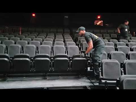
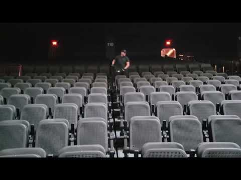
STEP 1. Make sure that all debris has been removed from the Section before moving the product.
STEP 2. Unlock chairs by depressing the foot release lever and lower them onto the deck (shown below).
NOTE: The operations team will have the choice to unpin and rotate the last row of chairs forward if desired.
STEP 3. Remove and store rubber gap closures (shown below).
STEP 4. Uninstall End and Front Curtains (if applicable).
STEP 5. Uninstall Removable Front Steps and Rear Access Steps.
STEP 6. Uninstall Hand Rails.
STEP 7. Disengage rear filler plates on last row from magnet holders and fold down onto telescopic deck.
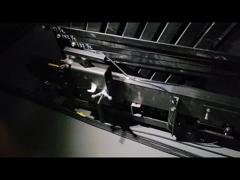
STEP 8. Use a small scissor lift with at least 2 people to remove the front beam support on the first row above the tunnel openings. This beam is attached with 12 black bolts.
STEP 9. Use a small scissor lift with at least 2 people to remove the rear beam supports on the rows above the tunnel openings. This beam is attached to the deck supports with 6 longer bolts with washers from the top of the beam and 6 nuts from the bottom of the deck supports.
NOTE: Do Not walk on the deck/aisle above the tunnel without these supports in place. Permanent damage to the beams and deck can occur as well as possible deck failure resulting in injury.
STEP 10. Disconnect cords from front section to rear section and from rear section to the receptacles near the ceiling of the rear walkway.
STEP 11. Remove aisle light clamps and carefully place into rear beam (where cord is routed through).
•Do not leave lights on deck, they will get damaged by the deck roller wheels.
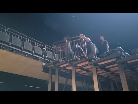
STEP 12. Uninstall End Rails, Front Rails and Rail Dogbones.
NOTE: To ensure operator safety, use a lift to remove end rails above shoulder height. Removing rails as shown in this video creates a fall hazard for personnel on the deck as well as a hazard for operators on the floor if the rail is dropped.
STEP 13. Install lift beam extensions and pin where applicable.
STEP 14. To close, release the first-row locks by disengaging the lever in the skirt panel.
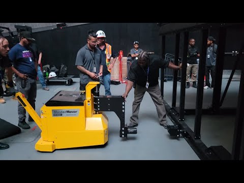
STEP 15. Attach the coupler to the front of the first row.
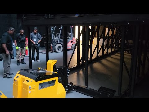
STEP 16. Line up the MasterMover to the front coupler. Drive the machine into the coupler and pin, press the lift limit button on the mover, then lift the mast to engage the couplers and transfer some of the row 1 weight to the drive wheel (shown below).
NOTE: Limiting the lifting of row 1 is important to ensure no damage will be done to the telescoping system.
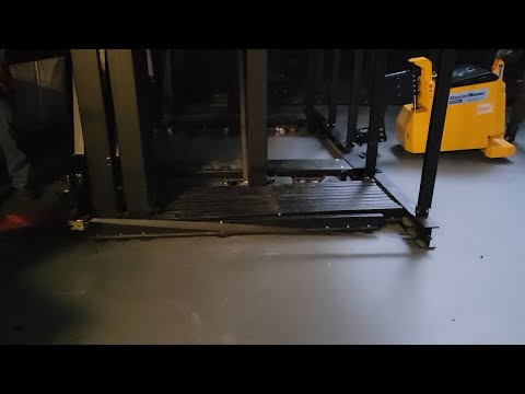
STEP 17. Begin pushing the system to the closed position in a safe and steady motion, steering to close the system straight (see below).
NOTE: Avoid making lunging motions as this is an unsafe practice.
STEP 18. Once the system is in the closed position, lower the MasterMover to disengage the couplers.
STEP 19. Remove the coupler from row 1 and use it to move other sections.
STEP 20. Attach Rachet Straps (see below).
STEP 21. Remove the pintel rod from the system to unsecure the telescopic from the floor.
STEP 22. Use air compressor to add air to the air lift system and allow to fill with air until posts are clearly off the floor.
STEP 23. Attach coupler to end of system and pin.
STEP 24. Line up the MasterMover to the coupler, then drive the mover into the coupler. Raise the mast of the mover to engage the couplers. (Make sure the row lift limiter is disengaged to move system around bowl).
STEP 25. Make sure that all debris has been removed from front of Section or Group before removing product.
STEP 26. Remove from in-use position and roll them into storage using the MasterMover and help from others to steer and control the system. Use spotters to prevent harm to operators around doors and walls.