Deploying portable units to in-use position
If assistance is needed please contact our Support Team at 888-GO-IRWIN (464-7946).
STEP 1. Make sure that all debris has been removed from in front of the section before moving the unit.
STEP 2. Check to make sure air-lifts are inflated. If needed, use the air compressor to air up the section for moving.
STEP 3. Install the female hitch coupler to the side of the rear lift beam. Pin coupler to hitch.
STEP 4. Line up the MasterMover to the coupler, then drive the mover into the coupler. Raise the mast of the mover to engage the couplers. (Make sure the row lift limiter is disengaged to move the system around the bowl).
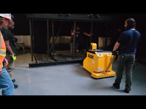
STEP 5. Remove from storage and roll them into place using the mover with help from others to steer and control the system. Use spotters to prevent harm to operators around doors and walls.
STEP 6. When in place, lower the MasterMover mast and remove it from the telescopic. Then slowly release air from the lifts to lower the section. Make final adjustment to position as needed as the telescopic may shift when letting air out.
STEP 7. Remove end coupler to use for moving other sections
STEP 8. Use Pintel system to lock into position (see below).
STEP 9. Remove Rachet Straps.
STEP 10. Make sure that all debris has been removed from the front of the Section or Group before opening the telescopic unit.
STEP 11. To open, release the first-row locks by disengaging the lever in the skirt panel.
STEP 12. Attach the coupler to the front of the first row (see below).
Note: the front coupler is shorter than the side couplers.
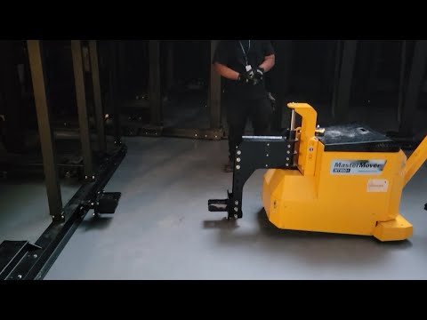
STEP 13. Line up the MasterMover to the front coupler. Drive the machine into the coupler, pin the coupler, press the lift limit button on the mover, then lift the mast to engage the couplers and transfer some of the weight from row 1 to the drive wheel.
NOTE: Limiting the lifting of row 1 is important to ensure no damage will be done to the telescoping system.
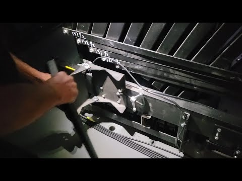
STEP 14. Begin pulling the system to the open position in a safe and steady motion, steering to open the system straight. Use laser from full open to closed points to follow a line to guarantee a straight opening (see below). Not following this process may result in uneven alignment, or difficulty fitting all 22 adjacent sections inside the opening of the building.
NOTE: Avoid making lunging motions as this is an unsafe practice.
NOTE: While the unit is opening, it is important to monitor the progress and look for any problems that might occur. Such as uneven right or left side progress, unexpected stops, or unfamiliar noises.
STEP 15. Once the system is in the open position, lower the mast of the MasterMover to disengage the couple, then remove the coupler from row 1.
STEP 16. Remove lift beam extensions on applicable sections.
STEP 17. In the open position re-engage the first-row locks using the lever in the skirt panel.
STEP 18. Perform a visual inspection to ensure all row locks are in the locked position prior to spectator use.
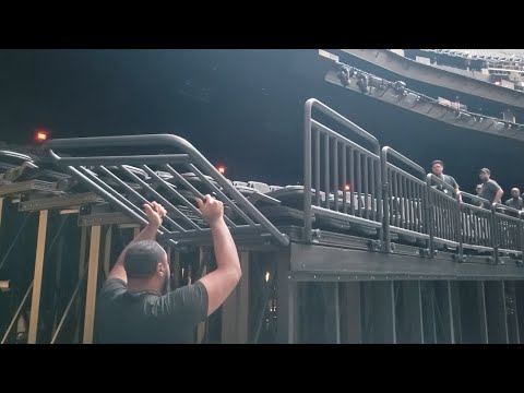
STEP 19. Install End Rails, Front Rails, and Rail Dogbones (see below).
STEP 20. Install Removable Front Steps and Rear Access Steps.
STEP 21. Install Center Hand Rails.
STEP 22. Carefully pull Aisle Light clamps out of storage position (inside riser beam void) and clamp them to the rear of end rail 13 inches above the decking.
STEP 23. Connect cords for light dimming and power from the rear of the front sections to receptacles on the front of the rear sections. Then connect light dimming and power cords from the rear section to receptacles near the ceiling of the rear walkway.
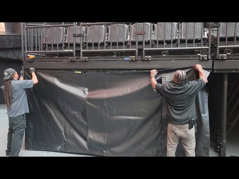
STEP 24. If applicable, install End and Front Curtains (see below).
STEP 25. Lift Chairs into upright and locking position. Make sure the last row chair on the concrete is also in the upright position and pinned as it may be rotated forward by operation staff.
STEP 26. Use a small scissor lift with at least 2 people to install the front beam support on the first row above the tunnel openings. This beam is attached with 12 black bolts.
STEP 27. Use a small scissor lift with at least 2 people to install the rear beam supports on the rows above the tunnel openings. This beam is attached to the deck supports with 6 longer bolts with washers from the top of the beam and 6 nuts from the bottom of the deck supports.
STEP 28. On the rear sections lift up the rear filler panel and engage with magnets to hold the panel in place.
NOTE: Do Not walk on the deck/aisle above the tunnel without these supports in place. Permanent damage to the beams and deck can occur as well as possible deck failure resulting in injury.